CED-1484
$44.95
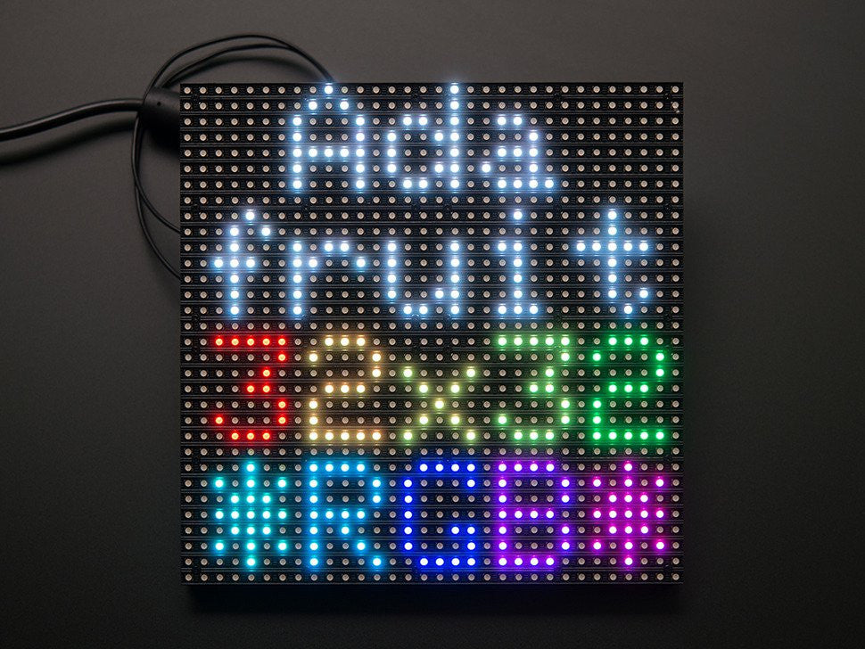
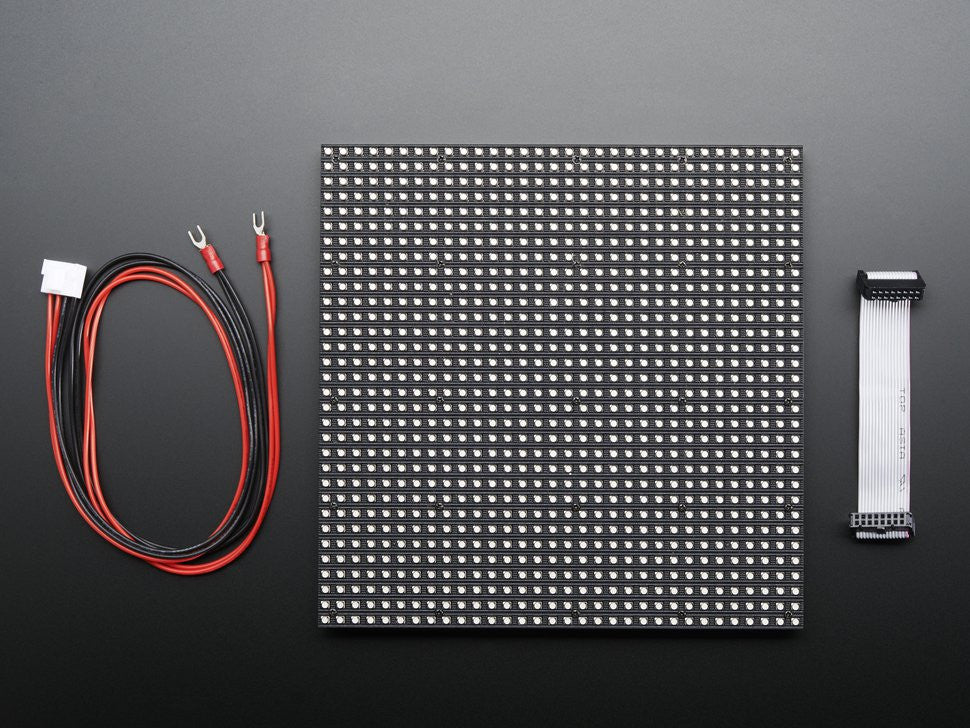
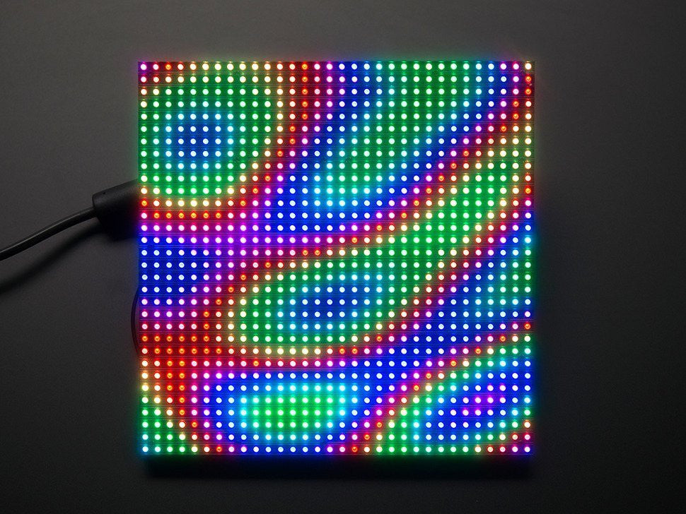
Bring a little bit of Times Square into your home with this sweet 32 x 32 square RGB LED matrix panel. These panels are normally used to make video walls on the sides of busses and bus stops, to display animations or short video clips. They have 1024 bright RGB LEDs arranged in a 32x32 grid on the front on a 6mm grid. On the back there is a PCB with a set of dual IDC connectors (one input, one output: in theory you can chain these together) and 12 16-bit latches that allow you to drive the display with a 1:16 scan rate.
These work great with the latest version of the Nootropic RGB Matrix Backpack!
These displays are technically 'chainable' - connect one output to the next input - but the Arduino example code does not support this (yet). It requires a high speed processor and more RAM than the Arduino has!
These panels require 13 digital pins (6 bit data, 7 bit control) and a good 5V supply, up to 2A per panel. We suggest our 2A regulated 5V adapter and then connecting a 2.1mm jack. Please check out our tutorial for more details!
Comes with: a single 32x32 RGB panel, one IDC cable and a power cable. If we happen to get them from the factory we also include 4 mounting screws and mini-magnets (it appears these are often mounted on a magnetic base).
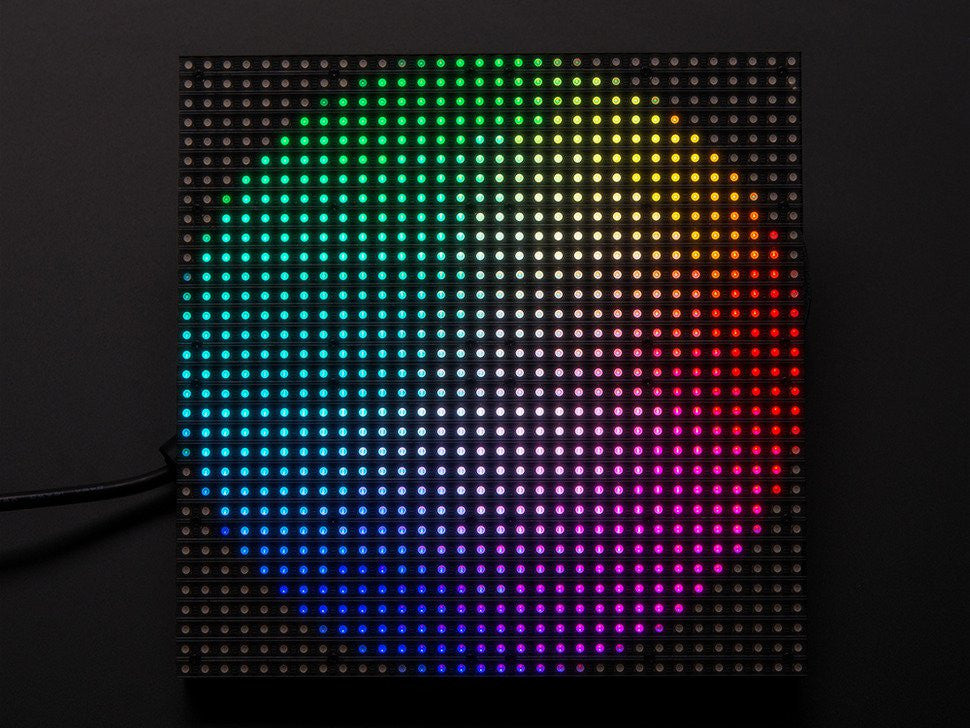
Keep in mind that these displays are designed to be driven by FPGAs or other high speed processors: they do not have built in PWM control of any kind. Instead, you're supposed to redraw the screen over and over to 'manually' PWM the whole thing. On a 16 MHz arduino, we managed to squeeze 12-bit color (4096 colors) with 40% CPU usage but this display would really shine if driven by any FPGA, CPLD, Propeller, XMOS or other high speed multi-core controller. The good news is that the display is pre-white balanced with nice uniformity so if you turn on all the LEDs it's not a particularly tinted white.
Of course, we wouldn't leave you with a datasheet and a "good luck!" Adafruit has a full wiring diagrams and working Arduino library code with examples from drawing pixels, lines, rectangles, circles and text. You'll get your color blasting within the hour! On an Arduino, you'll need 13 digital pins, and about 1600 bytes of RAM to buffer the 12-bit color image. At this time we do not have wiring documentation for the MEGA.
We don't have a spec or datasheet at this time. However, these are the specifications from the factory
Please Note: As of April 23rd 2018 this product is not ROHS compliant.
As of August 11, 2020 - We no longer include Magnetic Feet with this product